         Monthly Observatory Report
                                          for
                                      September 1995
COSTAR:
All engineering telemetry show nominal readings.
WFPCII:
1.1 Summary Of Major Accomplishments WFPCII continues to operate nominally throughout the month of Septemeber.
UV throughput was restored following the 6 hours CCD decontamination on day 264 (see Figure F2).
Science and Calibration observations continued to execute successfully.
FOC:
FOC is continuing the normal science program with GO and GTO cycle 4 proposals using the f/96 relay without problems.
For a picture of the Faint Object Camera click here.
FOS:
The FOS continued to execute a variety of GO, GTO, and CAL proposals during the month of Septemeber.
GHRS:
Both side 1 and side 2 of the GHRS are running well. One problem encountered only involves internal calibration exposures that use the side 1 flat field lamp. See section 1.2.
1.2 Summary of major problems
COSTAR:
COSTAR operations during the reporting period was nominal. Electrical and thermal monitors of the Instrument continue to show nominal values.
FOC:
In general: No major problems with FOC operations during the reporting period. Electrical and thermal monitors of the Instrument continue to show nominal values.
FOS:
No major problems were reported during the past month. On day 245 at 13:58 a FOS Binary Search target acquisition failed. The failure appears to be due to a problem in the proposal. Apparently the proposal was written to use a 14th magnitude star for the acquisition but a 20th magnitude was used instead.
GHRS:
1.2.1 During several resent calibration observations, exposures were terminated when too many lines of data were rejected after failing the data quality checks that are built into the GHRS flight software. This problem was only seen on side 1 observations that used the flat field lamp. It appears that, through some unknown mechanism, the side 1 flat field lamp is generating noise on detector 1. Detector 1 operation without the use of the flat field lamp appears to be nominal. A search of the data base identified only the detector calibration tests, and the threshold adjustment tests as using the flat field lamp. The threshold tests for the current cycle have been completed. The detector calibration tests are performed every three months. Before these tests are scheduled to be repeated, we will determine if use of the side 1 flat field lamp should be terminated.
1.2.2 Monitoring of GHRS carrousel reset activity is continuing. During the month of September there were 16 reset events for 1,128 commanded positions. Figure GHRS-F4 contains a plot which shows the accumulated number of times the carrousel is commanded to a new position and compares this rate to the accumulation of carrousel resets. The trend of both of these data sets is similar. Most recently the rate of reset events has increased. This rate will be watched to determine if this represents a new trend. Figure GHRS-F4 also includes a bar chart which associates reset activity to specific locations on the carrousel. This chart shows that the rate of reset events is higher at the lower region of the carrousel step scale. The rates shown in the region of the G140M grating are mis-leading since this is a little used optical element. A single reset in this region is rated higher than it would be in a more commonly used region.
WFPCII:
WFPCII operated normally throughout this month. Thermal spikes on the shutter/SOFA mount plate have been observed recently. These temperature spikes are a few degrees, and occur when the four incandescent lamps are turned On. Investigation show that the lamps themselves give out 0.6 watts each. However each lamp comes with a 10 watts resistor which is thermally coupled to the shutter/SOFA mount plate, and appear to be the cause for the temperature spikes. A 2000 seconds lamp On time produced a temperature delta of 5 degrees, and is well below the thermal limit and is not expected to produce any impact on the optical performance of the instrument. At this point there is no health and safety concern.
Several HSTARs were opened during this period in which WFPCII observations were affected: #5264, 5266, 5267, 5268, 5269, 5273, 5275, 5279, and 5298 were guide star acquisitions failing to coarse track, and were attributed to three different binary (bad) guide stars. #5294 was a LOL due to a large reversal bump on FGS1.
Flight Software Version 9.6 was installed on September 18, 1995 (day 95.261). The way of fallback for failed guide star (GS) acquisitions (acqs) has been changed since then. The following is what will happen when a scheduled GS acquisition fails:
1) For acquisitions on single GS: The acq will fail to gyro mode. 2) For acquisitions on an GS pair: a) Attempt to achieve coarse track on both guide stars in order to perform a coarse angle check. If coarse track cannot be achieved, the acq will fail to gyro mode. b) If the above coarse angle check passes, try to go to fine lock mode on single GS. The primary GS will be tried first. If fail to achieve FL on the primary GS, the secondary GS will be tried. If fail to achieve FL on the secondary GS, the acq will fail to gyro mode. c) If the above coarse angle check fails, the acq will fail to gyro mode. No acquisitions in coarse track or fallback to coarse track will be allowed.
During this month, search radius limit was exceeded on five different sets of guide stars, which caused 9 guide star acquisition failures. One GS pair was later acquired in coarse track mode. All 13 of the "no lock" and "degraded" acquisitions were due to double guide stars, and 6 different sets of guide stars were involved in these partial failures.
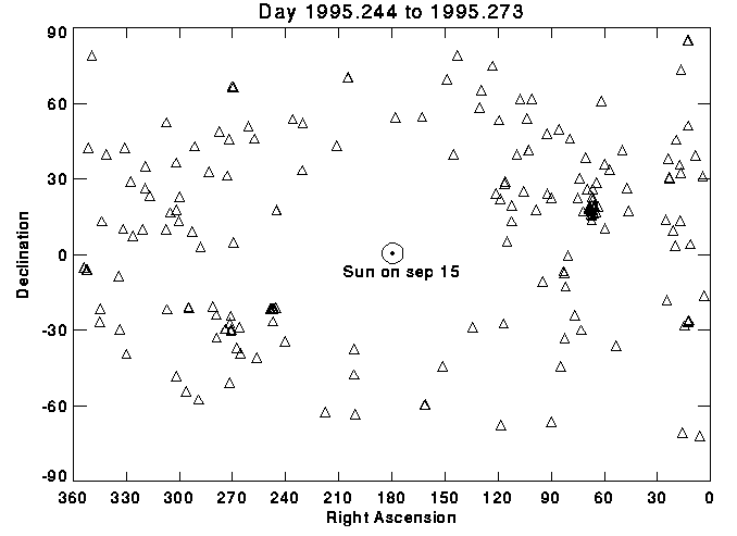
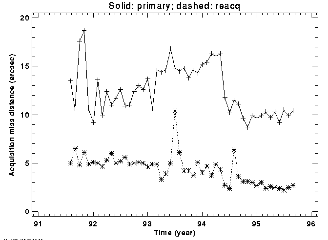
The sky distribution of pointings in this month is shown in Fig. 2.1. Fig. 2.2 shows the monthly average pointing miss for primary guide start acquisitions and reacquisitions. The pointing miss is measured from the location of the guide star found during search compared to the predicted position (start of the search). table 2.1 describes the statistics of guide star acquisitions. It takes into account both primary acquisitions and reacquisitions. "No lock" means that coarse track cannot be established or maintained. "Degraded mode" refers to the cases where the guiding mode falls back to coarse track when the commanded mode of the find lock cannot be established or maintained. "Search rad exc" refers to cases where the guide stars are not found.
The distribution of guiding modes by Science Instrument during scheduled exposures is given in table 2.2. for each scheduled exposure, the actual guiding mode is obtained from the engineering telemetry. The scheduled exposure time is subsequently summed up by guding mode for each SI to produce the distribution.
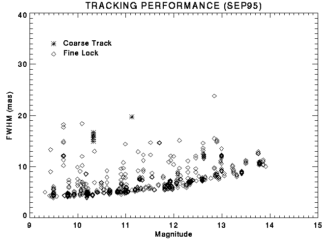
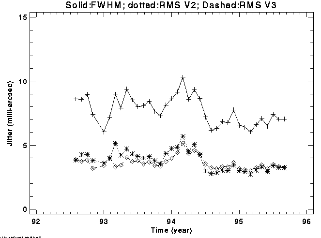
The full-width at half-max (FWHM) of jitter during observations are plotted as a function of the magnitude of the dominant guide stars in Fig. 2.4. the jitter is obtained from the motion of the dominant guide stars in the FGS. The rms of jitter along V2 and V3 axes is also calculated for each observation. The average of FWHM and rms of jitter over all observations in each month is given in Fig. 2.3 and shows no obvious trend.
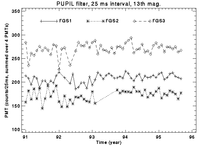
For each observation, the PMT sensitivity is calculated for each FGS in fine lock based on the PMT count rates and magnitude of the guide stars. The sensitivity is expressed in total counts of the 4 PMTs per 25 milli-seconds normalized for a 13th magnitude star with the FGS filter in pupil position. Fig. 2.5 shows the average sensitivities of each month since Janurary, 1991. The is no obvious trend. The variation of the sensitivities appears compatible to the error of the guide star magnitude.
2.2 Observations
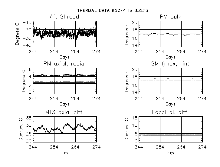
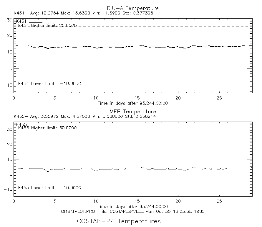
The temperature fluctuations of critical spacecraft components are shown in Figure 3.1. All temperatures are nominal.
3.2 Costar:
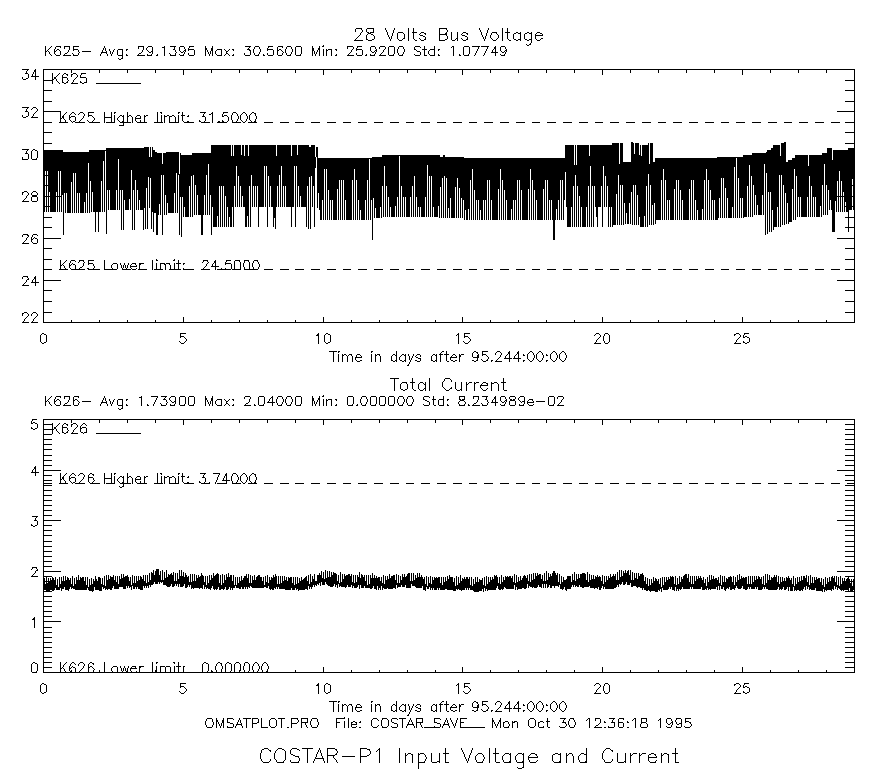
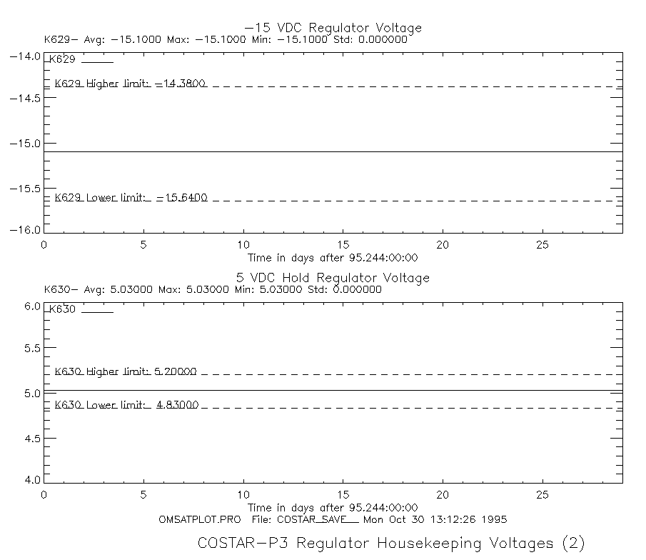
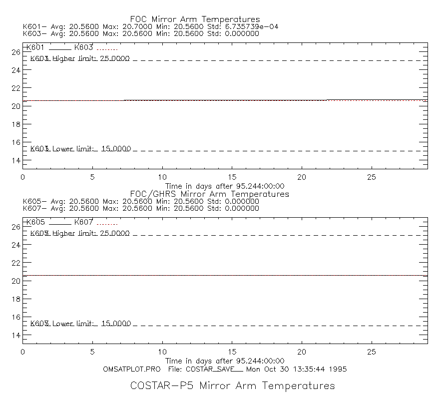
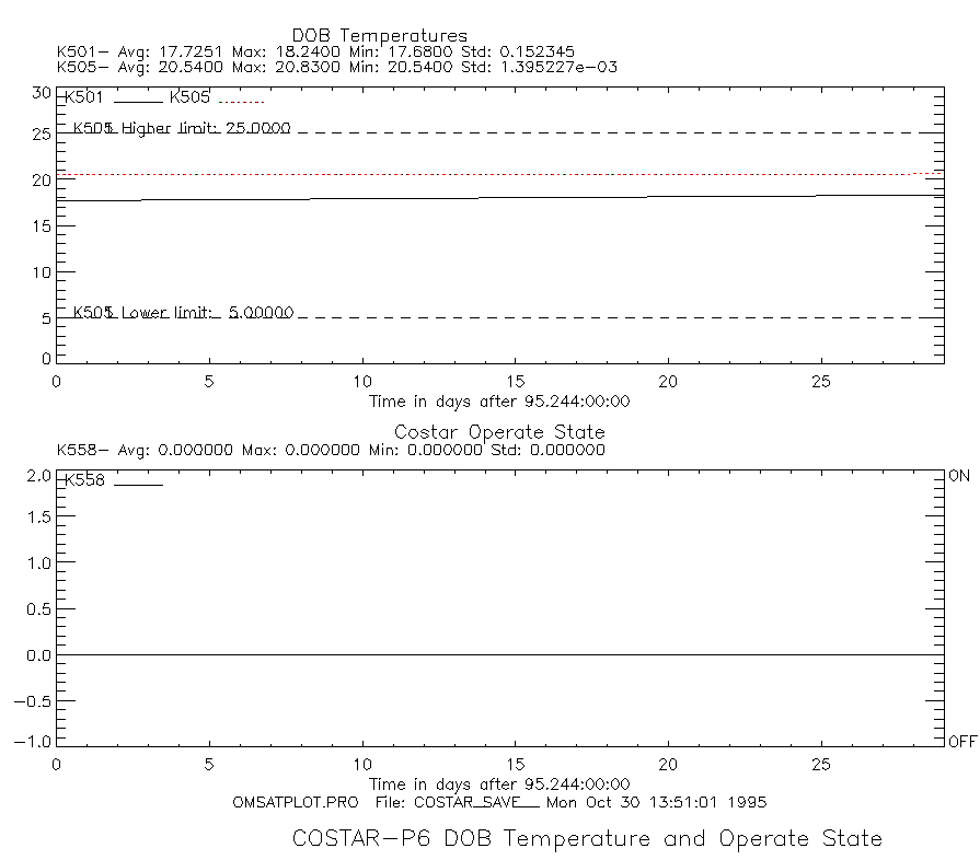
The Instrument continues to operate without problems: Evaluation of Error Logs show all voltages, currents, and temperatures within their nominal limits. Serveral plots of selected monitor points critical to the performance of the Instrument are an integral part of this report: costar-p1 : Input Voltage and Current shows the Input Voltage and total current profiles. costar-p2: and costar-p3 : illustrates the Regulator Housekeeping voltages. costar-p4 : contains the RIU-A and the Main Electronic Box (MEB) temperature profiles. costar-p5: and costar-p6 : shows the FOC/GHRS Mirror arm tempertures and the thermistor reading of the Deployable Optical Bench (DOB). costar-t1 contains a table of the latest position of all COSTAR mechanisms.
3.3 WFPCII:
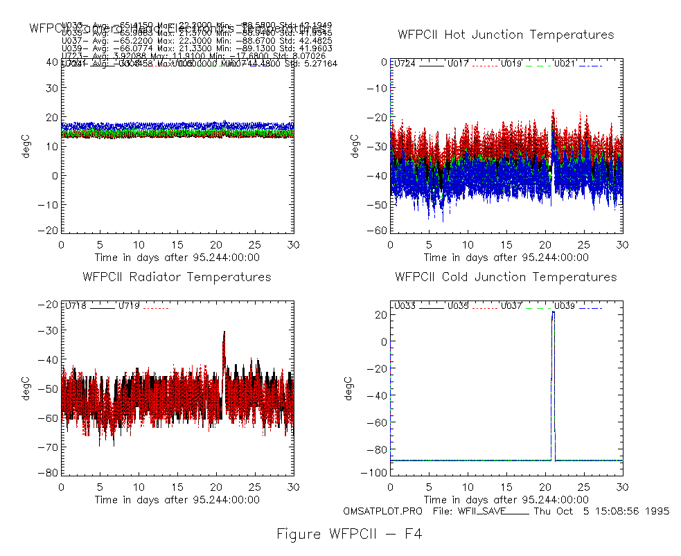
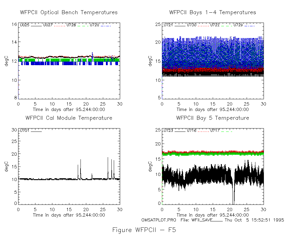
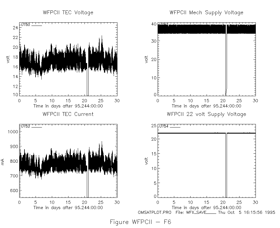
tables wfpc-ii t1, t2, t3 and show the Septemeber instrument statistics and profiles for cycle usage, power and temperature. All values are nominal and within limits unless otherwise noted. F4 shows the radiator cooling down to -74.2 C.
table t1 shows the cycles of various mechanisms and power supplies.
table t2 shows the lvps, mechanism, and tec voltage and current outputs.
table t3 shows the bays, optical bench, Bulkheads, Cold and Hot junctions, Camera Heads, Attach points, AFM, and Radiator temperature values.
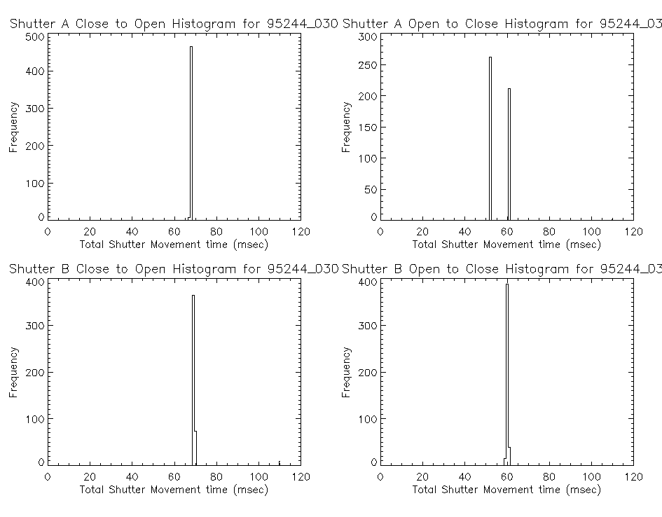
Figure f3 shows the frequency for various shutter close/open and open/close flight times.
Figure f4 shows the cold and hot sepctions, Camera Head, and Radiator temperatures.
Figure f5 shows the Bays, Optical Bench, and Cal Module temperatures.
Figure f6 shows the mechanism, tec and 22 lvps voltages and current.
Figure f7 shows the lvps, camera head, and UV Output Monitor voltages.
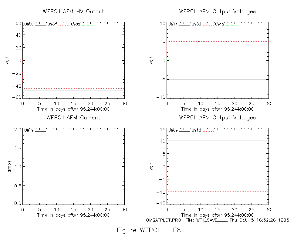
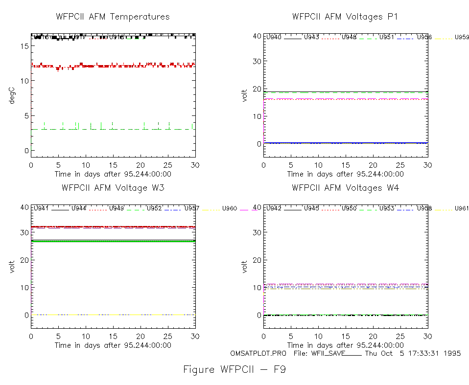
Figure f8 and Figure f9 shows the afm voltages and current
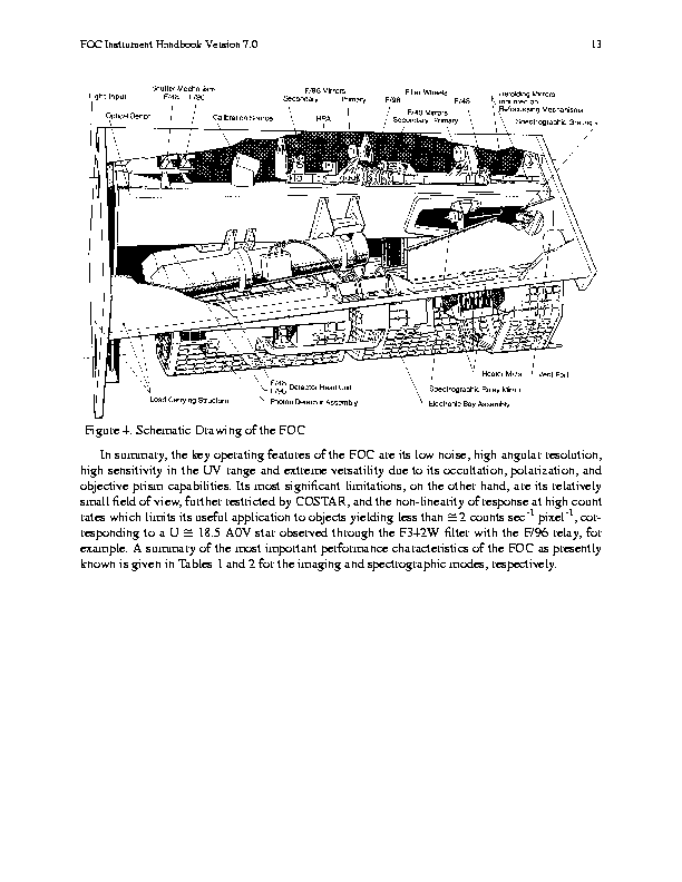
3.4 FOC:
FOC: The f/96 relay of the Instrument continues to operate without problems after the installation of COSTAR: Evaluation of Error Logs show all voltages, currents, and temperatures within their nominal limits.
Several plots of selected monitor points critical to the performance of the Instrument are an integral part of this report:
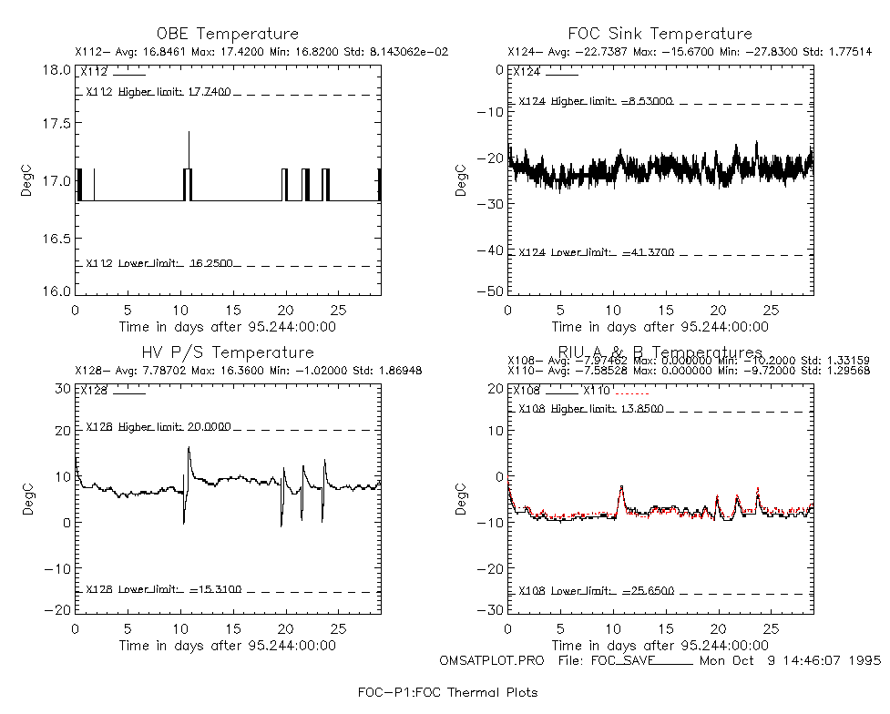
Four critical temperatures are shown foc-p1:foc thermal plots reflecting the thermal profile during the reporting period.
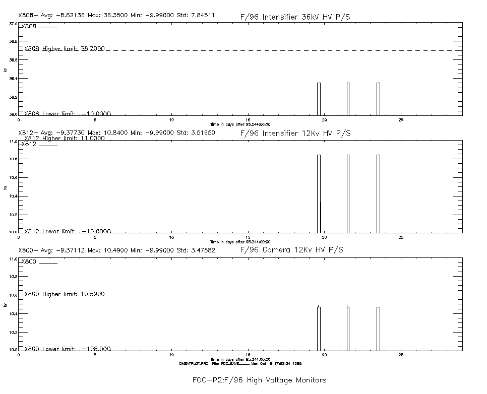
A set of three plots foc-p2:foc high voltage monitors illustrate the profile of the output voltages of the critical High Voltage Power Supplies for the FOC detectors. For a picture of the FOC Dectectors click here.
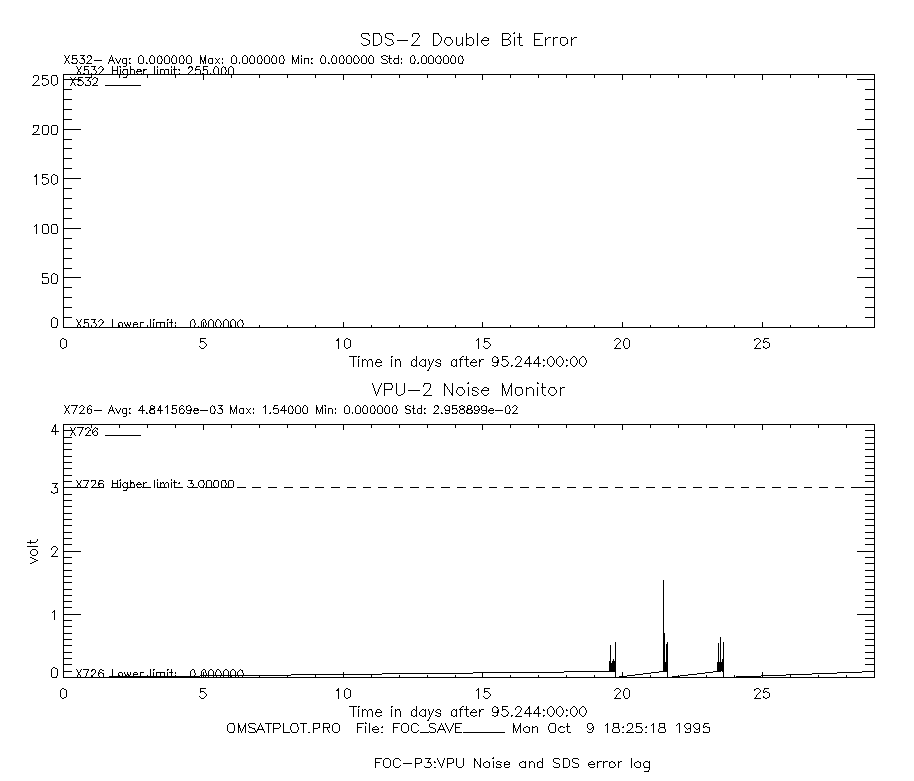
foc-p3:foc vpu noise and sds error log Both plots are focused on the health and safety of the Instrument. The Video Processing Unit (VPU) Noise level indicator summarizes the input signal as detected by the VPU. The peaks typically indicate passages throught the South Atlantic Anomaly (SAA).
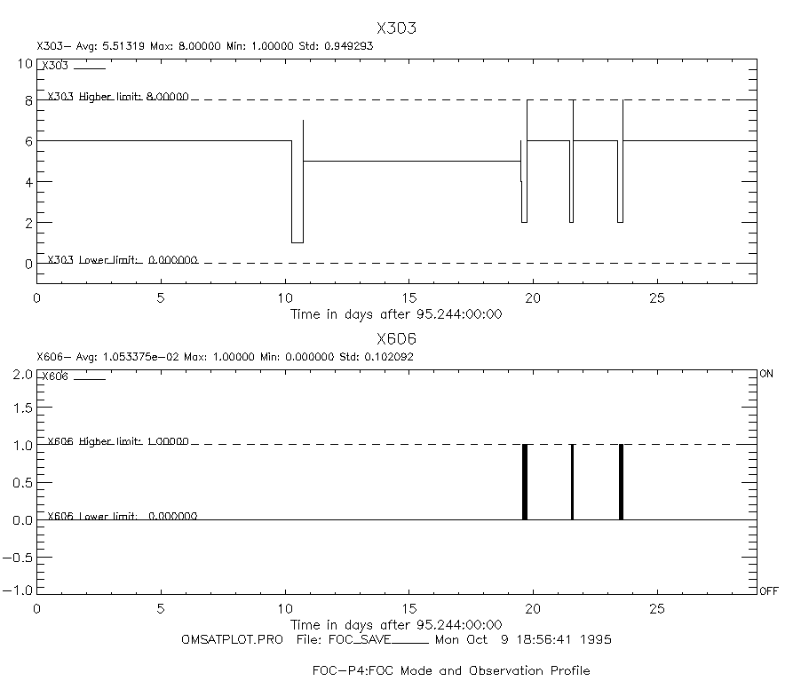
foc-p4:foc mode and observation profile shows the usage of the camera over the reporting period. A reading of the Thermal Control Table Number of "2" flags the time the FOC has been in the High Voltage Mode using the f/96 relay. The value of "1" indicates a reactivation of the F/48 Camera section.
Several Tables are inserted to keep track of operational statistics in particular of limited lifetime items: Table foc-t1 illustrates the statistics of the HV cycles and the hours the FOC was operated in the High Voltage Operate Mode. The same table foc-t1 shows the MIN/MAX/AVERAGE values grouped into the different operational modes: Safemode, Hold, and the High Voltage Operate Mode.
The foc-t2: mechanism cycle/usage table summarizes the usage of the mechanism during the reporting period and adds up the total number of cycles during Ground Testing and In-Orbit use.
A statistic on FOC f/96 Observations is given in Table foc-t2: mechanism cycle/usage table This table also keeps track of the number of loss of lock that occurred during a scheduled FOC observation time and adds up the time lost on target.
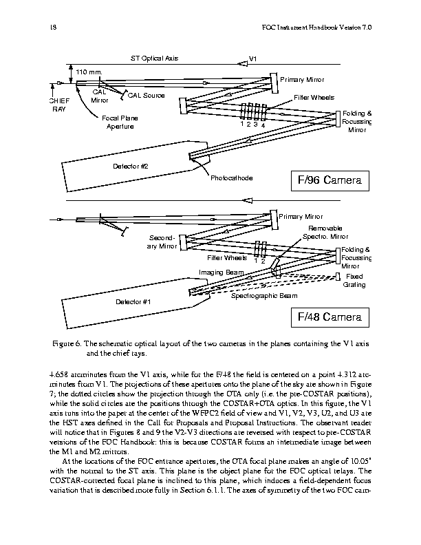
For a picture of the optical path and the FOC mechanism click here.
3.5 FOS:
Table fos-t1 shows the Cycle, Voltage and Miscellaneous summaries for the FOS for the month of Septemeber. There were no health and safety of operational limit violations for the month. No additional diodes were disabled during the month.
Table fos-t2 shows the thermal summary for the month. There were no health and safety or operational limit violations for the month.
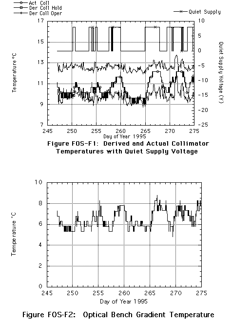
Figure fos-f1 is the standard plot of Collimator (predicted and actual) temperature (Y302) as a function of time. The predicted temperatures are based on algorithms for both the Operate (LVON) state and the Hold (LVOFF) states as a function of FOS aft shroud sink temperatures. The optical bench reacts in such a way as to be within +/- 1 deg C of equilibrium 24 hours after a transition. This plot suggests nominal thermal behavior for the detector as a whole even during the periods of continuous LVON.
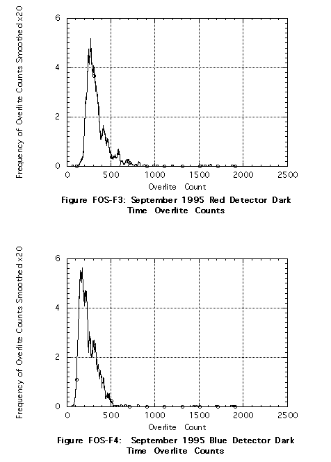
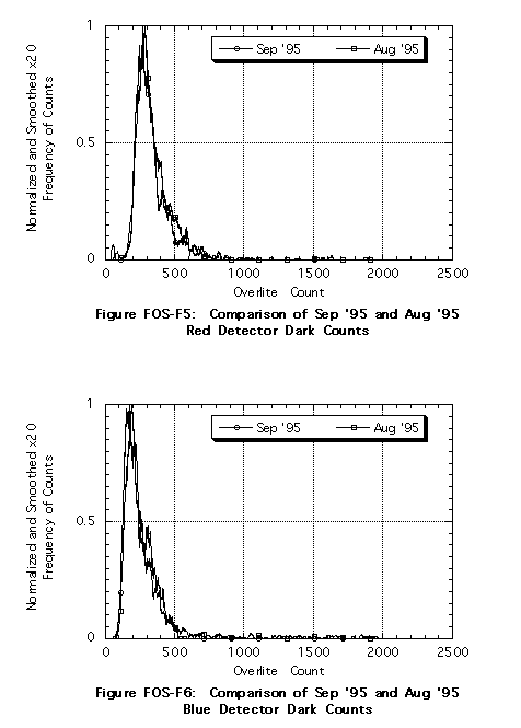
Figure fos-f2 shows a nominal optical bench gradient temperature for the month. Figures fos-f3 and f4 show the Red and Blue detector dark count data for the month. These plots are a representation of the Overlite counts from the FOS at all times that the detector is in Operate mode. Overlite is an engineering telemetry monitor of the total counts on the active detector array for the last 60 seconds. The data represented here occured after HV stabilization, after dead/noisy diode disabling, outside the SAA, with the FOS aperture door shut, and all lamps off. The data are therefore total dark counts in a 60 second period for all enabled diodes. Figures fos-f5 and f6 show the comparison of Septemeber's dark count data to August's. Septemeber's dark count data represent nominal performance.
3.6 GHRS:
All trended monitors appeared normal for this reporting period. The following tables and figures summarize activity of selected areas of the instrument.
Table ghrs-t1 is a cycle and use summary of the instrument mechanisms as well as a statistical analysis of main bus voltages and currents.
Table ghrs-t2 is a statistical summary of key instrument temperatures. All temperatures are within their normal range.
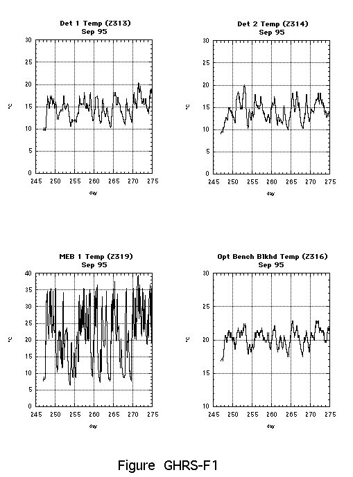
Figure ghrs-f1 contains plots of key instrumental temperatures. The temperature profiles for each detector and the optical bench are shown since these temperatures can affect optical stability. The temperature plot for MEB 1 is also included since large operational gradients on this monitor contributed to the intermittant failure on the side 1 low voltage power supply.
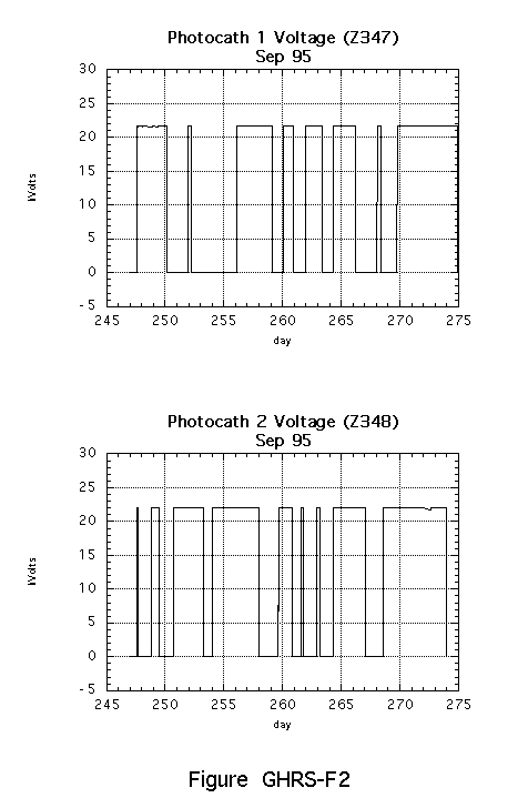
Figure ghrs-f2 shows the side 1 and side 2 power supply voltages for the month. These voltages remain very stable.
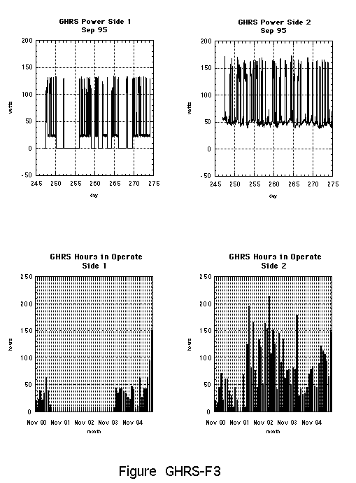
Figure ghrs-f3 contains monthly power profiles for each side of the instrument as well as historical summaries of hours spent in OPERATE mode.