|
POA - FOS: Geomagnetic Image Motion Problem
|
ST-ECF
|
|
The "GIMP"
"In orbit HST data taken with the red digicon detector of the FOS show
an image drift correlated with the Earth's magnetic field. This drift
occurs because the mu metal magnetic shield around the red digicon
does not shield adequately. The amplitude of the drift for a typical
orbit is roughly equal to the spectral resolution of the FOS. For data
taken with readouts every minute or two, resampling and shifting can
be used to remove most of the drift in the spectral direction. The
drift will compromise photometric accuracy at high signal to noise
ratios because the edge of the image of the aperture can drift beyond
the diode array in the direction perpendicular to the dispersion. The
microprocessor in the FOS can be re-programmed to counter the
geomagnetic drift by changing the deflection currents on a time scale
of one minute or less. In orbit data from the blue digicon show some
image drift that does not correlate well with the magnetic field. The
blue digicon mu-metal shield works better than the red side shield by
a factor of at least 3." From FOS Instrument
Science Report 066 Geomagnetic Image Deflection Problem in the Faint Object Spectrograph
See also:
ST-ECF Technical Reports relating to the GIMP.
FOS Instrument Science
Report 082: Lab Test Results of the FOS Detector Performance in a Variable External
Magnetic Field
Faint Object Spectrograph
Instrument Status and Performance Changes: 1990-1993: Keyes
FOS Geomagnetic Image Motion
Problem (or Why the Red Digicon is GIMPy and What to do about it)
Note that, some of these documents were drafts or proposals written
around the time that the GIM problem was discovered, therefore some of
the details may have been superseeded. However, they are presented
here as they contain information which never found its way into more
recent documents.
The Onboard Fix
The Space Telescope Science Institute and the FOS Investigation Definition
Team, set about correcting this Geomagnetically-induced Image Motion Problem
(GIMP) through a real-time on-board correction scheme. This correction
required modifications to almost all aspects of the HST ground system
as well as additional NSSC1 flight software and the use of an existing
software 'hook' in the FOS microprocessor firmware. From FOS
Instrument Science Report 098
See also:
The GIMP documents amongst the scanned
documents repository.
Minutes from FOS FSW meeting
09/05/91
FOS GIMP Correction Requirements
23/05/91
FOS GIMP Correction Flow Proposal
Preliminary PASS Requirements for
FOS GIMP Correction: Balzano, 06/06/91
FOS GIMP NSSC-I Flight Software Requirements
Review: Glen Foley, Flight Software Systems Branch 22/10/91
FOS GIMP Flight Readiness Review:
Adams, Balzano, Chance, Fitch, Foley, Schneider 16/12/92
Plots - Before and
After GIMP Correction: Fitch 16/12/92
Initial onboard test reports in HST Status Report 06/01/93 and HST
Status Report 07/01/93
Final GIMP Report: Fitch 19/03/93
Note that, some of these documents were drafts or proposals
written around the time that the GIM problem was discovered, therefore
some of the details may have been superseeded. However, they are presneted
here as they contain information which never found its way into more
recent documents.
Related STSDAS Tasks:
Diagram showing the GIMP correction
in the calfos pipeline
calfos
help pages.
Source of the gmpfos task in calfos.
To find the GIMP correction applied for any dataset try the STSDAS
task gimpcor.
But note that this relies upon the header information (infact it is
simply a subtask of calfos).
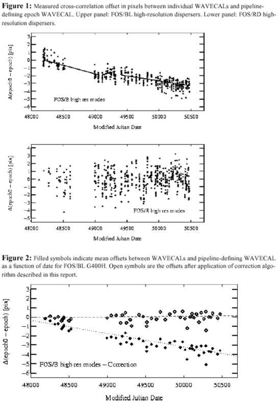
Zero Point Shifts
A significant, time-dependent, systematic shift of up to 7 quarter-stepped
pixels (1.75 diodes) in the zero-point of the FOS/BL wavelength scale has been confirmed
in FOS Instrument Science Report (ISR) CAL/FOS-149 (Rosa, Kerber, and Keyes).
Relative wavelength offsets within individual spectra are not affected by this shift.
FOS/BL wavelength zero-points shifted in a more-or-less monotonic
fashion from launch (April 1990) through de-commissioning (February 1997). An
approximate 7-pixel (1.75 diode) shift occurred over this time period. At any
given epoch the peak-to-peak scatter about the mean trend is +/- 1-pixel
(i.e., 10 times the measurement error). For high-dispersion gratings, 1
quarter-stepped FOS pixel corresponds to approximately 60 km/sec.
FOS/RD wavelength zero-points over the same time period present an
apparently random distribution with a peak-to-peak range of 7 quarter-stepped
pixels. Therefore, changes in FOS/RD wavelength zero-points are NOT confirmed
at the present time. Work continues to determine whether improved
characterization of the geomagnetic field and the onboard GIM correction can
remove any of this measurement scatter and thereby facilitate a possible
correction algorithm for FOS/RD.
Please note that no correction algorithm exists for FOS/BL PRISM, due
to the non-linearity of its wavelength scale, nor for FOS/RD observations.
Correction to Blue Zero Point Shifts
We provide an IRAF/STSDAS cl script (foswcorr.cl) and descriptive help file (foswcorrhlp.txt)
for use as a quick-fix to correct the wavelength files (.c0* files) for any FOS/BL
observation. Figures 1 and 2 (JPG - 42 Kbytes) illustrate the magnitude of the
observed shifts and the effectiveness of the quick-fix algorithm provided here.
Wavelength zero-point offsets caused by filter-grating wheel positioning uncertainties
are not removed by this correction algorithm. Currently corrections are not available
for FOS/BL PRISM nor for any FOS/RD observation.
 Obtain the cl script: foswcorr.cl (ASCII-text - 9 Kbytes). Obtain the cl script: foswcorr.cl (ASCII-text - 9 Kbytes).
Obtain the help file for the cl script: foswcorrhlp.txt (ASCII-text - 2 Kbytes).
Obtain the FOS ISR: CAL/FOS-149 (PDF - 53 Kbytes).
It is expected that the correction algorithm contained in the cl script
presented here will eventually be incorporated in standard calfos
processing. The availability of an updated calfos will be announced both
on the FOS WWW page and in the Spectrographs STAN when available. For the
present the cl script presented here is the ONLY procedure provided by STScI/ST-ECF for the correction of FOS/BL wavelengths.
Please refer to FOS ISR 149 for a thorough discussion of the correction
algorithm and other characteristics of the observed zero-point shifts.
Any additional correction algorithms, improvements to the FOS/BL
quick-fix procedure, or assessments of the impact of the observed shifts on
other instrumental calibrations will be announced in these pages.
Problems With the On Board Fix
The apparently random distribution of FOS/RD wavelength zero-points
stems from a number of problems in the implementation of the on-board
fix.
In order to remove the zero point shift in a given exposure therefore,
it is necessary to know the on-board correction applied, remove it,
and apply the appropriate correction. However in attempting to
construct a new CAL_FOS pipeline that would implement these
corrections, we ran into further problems.
- Header
Keywords regarding the on-board correction applied turn out to be
un-reliable.
- Pointing
information is often absent from WAVE-CAL datasets. Presumably at the
time the pointing was thought to be irrelevant for such exposures,
however this information is need for GIMP analysis.
- The instructions
up-linked to HST's on board computer (essentially coeffiecients of a
polynomial that specifies the X & Y deflection voltages at any time)
were not archived.
- The engineering
telemetry AEDP files contain the missing information, but not at
sufficient resolution.
See also:
Rectification of FOS wavelength
Scales, Kerber & Rosa in the June Issue of the ST-ECF
Newsletter
The New POA_CALFOS solution
The POA team at the ST-ECF now offer a calibration pipeline package
which automates the correction to the blue zeropoint shift and applies
some further corrections. See POA_CALFOS.
POA
| ESA | NASA | ST-ECF Archive | ESO
| ST-ECF | STScI
| Search
|