FOS: Images of the instrument after its succesful mission. ST-ECF
These pictures were taken during a visit to a storage facility of the Smithonian's National Air and Space Museum in June 1999. Later in the summer of 1999 the FOS was to be put on display in the museum. In preparation for that the original metal housing of the FOS had already been partially removed and replaced by plexi-glas covers exposing the interior structure of the FOS. From some parts the protective fabric (black) and the thermal blankets (gold) have also been removed.

VIEW OF THE FOS INSTRUMENT BOX
The light enters upper right corner (a
the entry section) following down the light path first in vertical direction and then, after being deflected by a mirror slanted by 23 degrees, towards the digicon detectors (large grey cylinder, c), passing the the filter grating wheel assembley (b) along the way.The ventilation system is visible at the bottom (d). An exploded diagram of the optical path is also available. Note the complex truss structure providing mechanical support for the different optical and electrical components of the instrument. The box has about the size of a phone booth.

CLOSE-UP OF THE ENTRY SECTION OF THE OPTICAL PATH
Visible are the aperture wheel, c, the polarizer assembly, b, and the mounting bracket of the deflection mirror, a (the
mirror itself had been removed for reflectivity tests). The silver knob, e, on top of the box is part of the hatch mechanism securing the instrument inside the HST. The entrance itself is behind the casing at d.

An exploded diagram of the optical path and a diagram of the FOS apertures projected onto the sky are also available for comparison.

CLOSE-UP OF THE ENTRY SECTION OF THE OPTICAL PATH II
Visible are part of the entry port, a, the aperture wheel, b, the polarizer assembly, c, and the deflection mirror, d, now back in its original position.

CLOSE-UP OF THE MIDDLE SECTION OF THE OPTICAL PATH
Starting from the bottom the following can be seen: two light baffles, a and b, with two holes each (one for the red and blue channel of the instrument), the Filter Grating Wheel Assembly (FGWA) with its positioning system, the
holes (eg. c and d) create a pattern read by a light sensitive cell providing the actual position of the FGWA. Mounted on the wheel are the different gratings (white glass slices, eg e).

CLOSE-UP OF THE FILTER GRATING WHEEL ASSEMBLEY
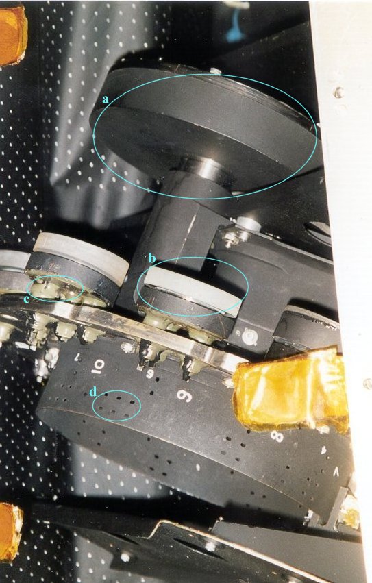
Detailed view of the Filter Grating Wheel Assembly (FGWA) with its positioning system, the holes (eg. d) create a pattern read by a light sensitive cell providing the actual position of the FGWA. Mounted on the wheel are the different gratings (white glass slices, eg. b). The greenish gray material (eg. c) is glue used to secure the screws in place. The black disk at the top, a, is a balancing weight.

CLOSE-UP OF ONE OF THE GRATINGS
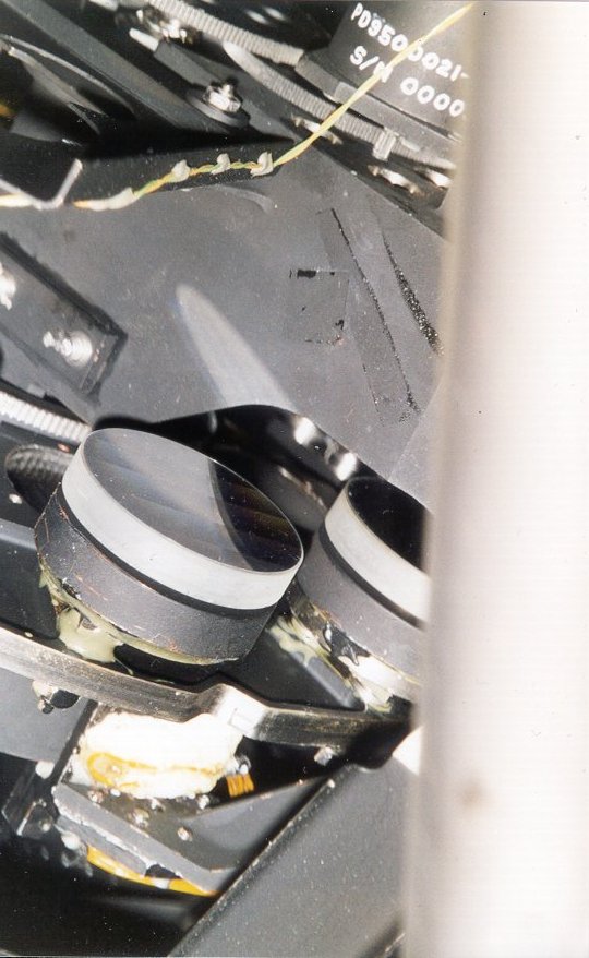
Detail of the
FWGA showing the reflective surface of one grating.

CLOSE-UP OF THE DIGICON ASSEMBLEY
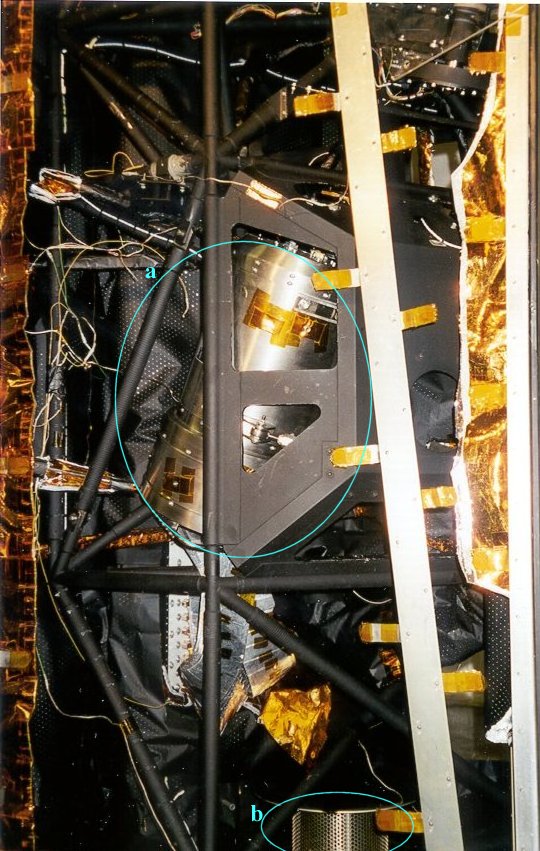
One of the two digicon detector (silver, a) in its mounting cradle (black). Originally also wrapped in black fabric the metallic housing of the digicon has been exposed. The sieve-like structure at the bottom is part of the instruments ventilation system, b, letting the air escape during launch. See also this
schematic diagram of the digicon detecors.

Further explanation of the instrument can be found in this brief technical overview.

More pictures of FOS and the digicons during construction some two decades earlier.


POA | ESA | NASA | ST-ECF Archive | ESO | ST-ECF | STScI | Search

[STECF HOME]